ORIGINAL RESEARCH |
https://doi.org/10.5005/jp-journals-10024-3079 |
The Low Window Technique: Comparison between Manual and CAD/CAM-guided Design
1,2Studio Dentistico Zaniol, Via Lodovico Boschieri, 45/4, 31035 Crocetta del Montello, Treviso, Italy
3Department of Cariology and Comprehensive Care, New York University College of Dentistry, New York, United States
Corresponding Author: Terry Zaniol, Studio Dentistico Zaniol, Via Lodovico Boschieri, 45/4, 31035 Crocetta del Montello, Treviso, Italy, Phone: +39 423665021, e-mail: tzaniol@outlook.it
How to cite this article: Zaniol T, Zaniol A, Ravazzolo S. The Low Window Technique: Comparison between Manual and CAD/CAM-guided Design. J Contemp Dent Pract 2021;22(4):400–405.
Source of support: Nil
Conflict of interest: None
ABSTRACT
Aim: The aim of this bench study was to provide quantitative data addressing the difference between the manual low window design and the corresponding computer-aided design and computer-aided manufacturing (CAD/CAM)-guided design.
Materials and methods: Five cone-beam computed tomography (CBCT) scans of as many patients (two males and three females, age range: 61–78 years) with partially edentulous maxilla to be rehabilitated through sinus augmentation, one- or two-step implant placement, and implant-supported prostheses were used to 3D-print the corresponding five maxillary stereolithographic models. Five independent highly skilled maxillofacial surgeons, who were provided with the patients’ orthopantomographs, drew on the models the access windows for sinus augmentation according to the “high” (standard) and the low window design both by free-hand and using a surgical guide prepared by computer-guided design. Accuracy and inter-operator variability were analyzed.
Results: The results of this study showed that the manual design is associated with a clinically relevant shift in the low window shape, size, and positioning compared with the CAD/CAM-based positioning. All four directions (apical, coronal, mesial, and distal) showed on average the same extent of placement error (approximately 3 mm). Overall, the intra-operator variability was very similar, and measurements were not influenced by the operator (low inter-operator variability).
Conclusion: The compromised accuracy and reproducibility in the manual design may limit the advantages of the low window technique. Thus, within the limits of this study, the computer-guided approach should be preferred vs the manual approach when performing a low window sinus lift. This may limit intra- and postoperative complications, as well as patient discomfort.
Clinical significance: The “best option” CAD/CAM-guided design should be chosen when performing a low window sinus lift because it reduces discrepancies in selected parameters both between and within groups. This should facilitate the achievement of better results by dentists who have insufficient experience performing implant surgery.
Keywords: Computer-aided design, Computer-aided manufacturing, Guided surgery, Low window approach, Sinus augmentation.
INTRODUCTION
Sinus augmentation is one of the most popular techniques for surgical bone grafting, facilitating implant placement in the atrophic maxillae.1 This technique has been extensively investigated since 1980,2–4 and was shown to be highly predictable and successful.5,6 Over the years, it was refined to reduce invasiveness, discomfort, and surgical complications.7–11 Sinus augmentation can be performed either according to the transalveolar (crestal) or the lateral window approaches. Under severe bone atrophy, a lateral approach may be preferred. The “standard criteria” for positioning the lateral window include placing its inferior border at approximately 3 mm from the sinus floor. Posteriorly, the window can extend over the tuberosity. Its anterior border is placed at approximately 3 mm from the anterior sinus wall.1 The window height should range between 15 and 18 mm (Fig. 1A).12 Clinical literature reporting about lateral sinus augmentation demonstrates great variability among window shape, design, size, and position.1,12–14 A rationalized and standardized window design may instead reduce operative errors, complications (i.e., Schneiderian membrane laceration, post-surgical patient discomfort) as well as operator fatigue.1,12,15–18 Recently, a rationalized approach—the “low window sinus lift”—was developed for placing the lateral window in a position limiting the aforementioned risks.19,20 As shown in Figures 1B and D, the principle is to place the window as low and mesial as possible. The lower osteotomy and mesial lines are placed flush with the sinus floor and anterior wall, respectively. The window height should not exceed 6 mm, to avoid injuring intra-osseous anastomoses. The distal osteotomy line is placed in correspondence to the most distal planned implant. This allows limiting flap preparation to a linear incision without the requirement for release incisions, preserving the attached gingiva of the most distal residual element present. The low window sinus lift approach reduced the risk of membrane perforation and patient discomfort in a clinical setting.19,20 Authors highly recommend that the design and position of the low window antrostomy should be based on the use of three-dimensional (3D) digital software, and a surgical template created for allowing the surgeon to perform the osteotomies.19 This approach is accurate and has shown promising clinical results, potentially limiting Schneiderian membrane perforation, surgery time, and patient post-surgical discomfort in both the standard and the low window settings.19,21,22 The manual window design, even if it is performed by highly skilled and experienced surgeons based on the use of cone beam computed tomography (CBCT) images, may introduce high error and variability, thus limiting the advantages of the low window technique, owing to the clinical risks and consequences of an incorrectly positioned window. Thus, the objective of this study was to determine the most appropriate technique (i.e., manual vs computer-guided) for the low window approach.

Figs 1A to D: (A) “Standard window” criteria, adapted from Danesh-Sani et al.;1 (B) Low window sinus lift antrostomy. The lower osteotomy line (blue) is flush with the sinus floor. The upper one (dark green) 6 mm higher. The light green line is flush with the sinus anterior wall. Distal one (red) is placed in correspondence with the most distal implant;20 (C) “Standard window” osteotomy; (D) Low window osteotomy
MATERIALS AND METHODS
CBCT scans of five patients (two males and three females, age range: 61–78 years) with the partly edentulous maxilla, for whom the rehabilitation plan included the delivery of an implant-supported prosthesis and sinus augmentation before or concomitant to implant placement in the posterior maxilla, were used. These scans were performed with a 3DIEMME RealGUIDE v5.0 scanner (3Diemme Bioimaging Technologies, Como, Italy). The output data were exported in digital image communications in medicine format, and five maxillary stereolithographic models were 3D-printed using the Objet EDEN 260VS printer (Stratasys, MN, USA). Orthopantomographs were obtained from each of the five patients. The study was conducted at the private clinic of the corresponding author.
Manual Design of Lateral Windows
Five independent physicians were previously instructed to attend an hour lesson focused on the review of Danesh-Sani et al. about the maxillary sinus floor elevation1 and the article of Zaniol and Zaniol evaluating the low window sinus lift.20 At the end, the physicians were examined by requiring them to draw the high and low window approaches. Five physicians received identical materials for the manual lateral window design, (1) five numbered patient data packages each containing one CBCT disc and print, and one orthopantomography; (2) five numbered corresponding stereolithographic maxillary models; (3) one black pencil for the standard window design; (4) one blue pencil for the low window design; (5) one green pencil for the guided low window design; (6) one red pencil for the guided standard window design; (7) one 15-mm periodontal probe; and (8) instructions for the positioning of the window. Standard window positioning criteria were supplied as an inferior border—distance of 3 mm from the sinus floor; anterior border—distance of 3 mm from the anterior sinus wall; height—15–18 mm; the horizontal axis of the window template must be placed in parallel to the sinus floor. Low window positioning criteria were supplied as an inferior border—in correspondence to the sinus floor (horizontal axis of the window template must be parallel to the sinus floor); anterior border—in correspondence to the anterior sinus wall; height—not exceeding 6 mm. The five physicians were asked to represent the two windows on the five models, each operator was instructed to respect the numbering order of the stereolithographic models (starting with number 1 and ending with number 5), beginning with the standard windows (Fig. 2B) followed by the low windows. Windows were consecutively designed under good lighting conditions.
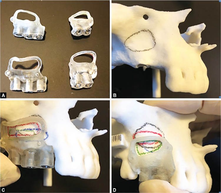
Figs 2A to D: Manual and guided window design; (A) Surgical guide manufactured through 3-D printing; (B) Manual standard window design; (C) Guided standard window design; (D) Guided low window design
Computer-guided Design of the Lateral Window
The computer-guided approach was followed by providing the physicians with the surgical guides of both the window designs. A single physician (Terry Zaniol) imported the CBCT data of the five patients into the 3DIEMME RealGUIDE v5.0 software to project a surgical guide for the design of the standard or low window according to the criteria provided to the manual operators. Each surgical guide (one standard and one low window guide for each model) was printed using the Objet EDEN 260VS printer (Fig. 2A). The guide was fitted onto the stereolithographic models to trace the standard window with a red pencil (Fig. 2C), and the low window with a green pencil (Fig. 2D). The single operator followed an identical numbering order and the criteria for lighting and consecutively imposed to the manual operators.
Outcome Measurements
The position of either the standard or low manual window on the stereolithographic models, was compared with that of the corresponding computer-guided window as follows. For each manually designed window and its corresponding computer-guided window, the maximal mesial, distal, apical, and coronal distances between the windows were measured using a periodontal probe, approximating each measure to the inferior or superior mm unit. The probe was positioned either parallel to the bone ridge (for the apical-coronal measurements) or at a 90° angle to the bone ridge (for the mesiodistal measurements). This was performed to measure the distance of the most external point (e.g., in the coronal direction) of the manual window, to the most external point of the computer-guided window in the same direction (Fig. 3). The minimal measuring unit of the dental probe was 1 mm; thus, technical replicates of the measurements were not performed. Notably, when applied with the aforementioned criteria, it yielded consistent results.

Figs 3A and B: To measure the distance of the most external point of the manual window to the most external point of the computer-guided window in the same direction. (A) The probe was positioned either parallel to the bone ridge (apical-coronal measurements) or (B) at a 90° angle to the bone ridge (mesiodistal measurements) (A: coronal distance, B: mesial distance)
Data Analysis
Mean values ± standard deviations were calculated for the apical, coronal, distal, and mesial distances from all replicates (five operators), both for the standard and low window designs. An overall mean for all five stereolithographic models was further calculated. The inter- and intra-operator variability in the window positioning was also looked into. Mean overall placement errors (measured in mm) were compared for each type of window between the five operators to assess the intra-operator variability in the window positioning. A Shapiro–Wilk test was applied to determine the normality of all data sets. One-way analysis of variance (ANOVA) and Mann–Whitney U tests were used for the analysis. Statistical analysis of the mean distance values was performed to determine significant differences.
RESULTS
Fig. 4 shows the mean distances between the manual and computer-guided window designs in the apical, mesial, distal, and coronal directions. Compared with the “best option” computer-guided approach, the mean positioning error was consistently ˜3 mm. There were no significant differences between all four directions of the low vs standard window techniques, except for a significantly lower positioning error in the distal direction in the standard window approach (p <0.005).

Fig. 4: Mean (± standard deviation) distance between the apical, mesial, distal, and coronal directions of the guided vs manual window designs; black, standard window; grey, low window; ***p <0.005
Figs 5A to D show the inter- and intra-operator variability in the window positioning and include error ranges (Figs 5A and B) in all four directions for each operator, as well as single error values measured in all four directions (Figs 5C and D) for each operator. There was no statistically significant difference in the positioning errors between operators, except for operator 5 who performed significantly worse in the low window approach (p <0.05). The results showed that the manual approach is associated with a clinically relevant shift in the low window shape, size, and positioning compared with the “best option” computer-aided design and computer-aided manufacturing (CAD/CAM)-based positioning. The intra-operator variability was very similar, and measurements were not influenced by the operator (apart from operator 5, who performed significantly worse in the low window approach).

Figs 5A to D: Inter- and intra-operator variability. (A) Low window approach and (B) standard window approach box plots range of errors (mm) in all directions in the manual vs guided window placement in operators (Op) 1–5; (C) Low window approach and (D) standard window approach dot plots, single errors in all directions; **p <0.05
DISCUSSION
Several in-vitro and in-vivo studies have demonstrated the high accuracy and efficacy of computer-guided dental and maxillofacial surgery.23–25 Moreover, studies have emphasized that the use of a CAD/CAM surgical guide reduces discrepancies among operators performing oral surgery, regardless of their level of experience.26,27 However, several studies did not report the superiority of computer-guided procedures over conventional procedures in terms of safety and clinical outcomes.28,29 Hence, whether the computer-guided approach offers clinical advantages is currently under debate. Nevertheless, a consensus has been reached, confirming that computer-guided procedures are recommended in cases with critical anatomic situations (e.g., an implant to be placed adjacent to the mandibular nerve).28 Sinus lifts, owing to the several maxillary structures involved and the aforementioned potential complications, are highly indicated by a rationalized computer-guided approach. Mandelaris and Osman et al. suggested the use of a modified surgical guide for implant placement by integrating its lateral window frame to improve precision in window outlining during sinus lift procedures.21,30 The low window design allows the use of any surgical guide efficiently. On the contrary, a higher window position may interfere with the correct positioning of any such guide due to the inclination of the vestibular ridge.19
Our results showed that all four directions (apical, coronal, mesial, and distal) displayed on average the same extent of placement error. Notably, there was no significant difference observed in the manual design error compared with the standard window, except for the distal direction. Similarly, Park et al. have shown that using the CAD/CAM surgical guide reduced discrepancies among operators performing implant surgery regardless of their level of experience.26 Standard deviation values revealed high variabilities in all four directions, and in both low and standard window designs. Overall, measurements were not influenced by the operator except for operator 5 who performed significantly worse in the low window approach. These results highly correlate with the ones reported by Rungcharassaeng et al. showing that the angular and linear deviations are not affected by the operator’s level of experience.27 The variability and irreproducibility of the manual approach may limit the advantages of the low window technique. An error of window positioning in the apical-coronal direction of a few mm may induce several outcomes. For example, if the antrostomy is excessively apical, a greater flap lift is necessary. Consequently, a linear incision is insufficient, and vertical release incisions of the mucogingival tissue are required to elevate the flap. This is associated with a greater post-surgical inflammatory response, leading to more swelling, hematoma, and pain. Ultimately, this results in an overall greater discomfort for the patient. Furthermore, the elevation of a greater flap may be hindered by the tension of the muscular tissue of the cheeks and lips, requiring greater retraction of the patient’s vestibular tissues. If the antrostomy is excessively apical, the risk of intercepting the arterial anastomosis between the infraorbital artery and the posterior superior alveolar artery is increased. Therefore, the risk of intra- or post-surgical hemorrhage also increases. If the apical limit is excessively coronal, the surgeon may not sufficiently detach the Schneiderian membrane. This may lead to an under-filling of the sinus cavity with bone grafting biomaterial. The newly formed sinus floor should have a distance of ≥13–15 mm from the bone crest to cover the apexes of the concomitantly or subsequently placed implants. If the antrostomy is positioned a few mm toward the mesial direction, the alveolar bone is found rather than the maxillary sinus. Moreover, if the antrostomy is positioned a few mm towards the distal direction from the anterior recess, detachment of the Schneiderian membrane may become more difficult.
The limitation of the present study is that the variability and reproducibility of window positioning were only measured in the manual approach and not in the computer-guided approach. The latter was considered a “best option”, based on the current literature and previous studies.19,20 Therefore, the results of this bench study should be further investigated in a clinical setting.
CONCLUSION
In conclusion, within the limits of this study, the computer-guided approach should be preferred vs the manual approach when performing a low window sinus lift and regarded as a “best option”. This may limit intra- and post-operative complications, as well as patient discomfort.
CLINICAL SIGNIFICANCE
The “best option” CAD/CAM-guided design should be chosen when performing a low window sinus lift because it reduces discrepancies in selected parameters both between and within groups. This should facilitate the achievement of better results by dentists who have insufficient experience in performing implant surgery.
REFERENCES
1. Danesh-Sani SA, Loomer PM, Wallace SS. A comprehensive clinical review of maxillary sinus floor elevation: anatomy, techniques, biomaterials and complications. Br J Oral Maxillofac Surg 2016;54(7):724–730. DOI: 10.1016/j.bjoms.2016.05.008.
2. Tatum H Jr. Maxillary and sinus implant reconstructions. Dent Clin North Am 1986;30(2):207–229.
3. Tatum OH Jr, Lebowitz MS, Tatum CA, et al. Sinus augmentation. Rationale, development, long-term results. N Y State Dent J 1993;59(5):43–48.
4. Boyne PJ, James RA. Grafting of the maxillary sinus floor with autogenous marrow and bone. J Oral Surg 1980;38(8):613–616.
5. Del Fabbro M, Wallace SS, Testori T. Long-term implant survival in the grafted maxillary sinus: a systematic review. Int J Periodontics Restorative Dent 2013;33(6):773–783. DOI: 10.11607/prd.1288.
6. Chiapasco M, Casentini P, Zaniboni M. Bone augmentation procedures in implant dentistry. Int J Oral Maxillofac Implants 2009;24 Suppl:237–259.
7. Esposito M, Felice P, Worthington HV. Interventions for replacing missing teeth: augmentation procedures of the maxillary sinus. Cochrane Database Syst Rev 2014;(5):CD008397. DOI: 10.1002/14651858.CD008397.pub2.
8. Summers RB. A new concept in maxillary implant surgery: the osteotome technique. Compendium 1994;15(2):152, 154–156, 158 passim; quiz 162.
9. Cosci F, Luccioli M. A new sinus lift technique in conjunction with placement of 265 implants: a 6-year retrospective study. Implant Dent 2000;9(4):363–368. DOI: 10.1097/00008505-200009040-00014.
10. Fugazzotto PA. The modified trephine/osteotome sinus augmentation technique: technical considerations and discussion of indications. Implant Dent 2001;10(4):259–264. DOI: 10.1097/00008505-200110000-00009.
11. Trombelli L, Franceschetti G, Stacchi C, et al. Minimally invasive transcrestal sinus floor elevation with deproteinized bovine bone or β-tricalcium phosphate: a multicenter, double-blind, randomized, controlled clinical trial. J Clin Periodontol 2014;41(3):311–319. DOI: 10.1111/jcpe.12210.
12. Testori T, Wallace SS, Monteverdi A, et al. Complications: diagnosis and management. In: Testori T, Weinstein R, Wallace SS, editors. Maxillary Sinus Surgery and Alternatives in Treatment. Berlin, Germany: Quintessence Publishing; 2009. pp. 311–323.
13. Stern A, Green J. Sinus lift procedures: an overview of current techniques. Dent Clin North Am 2012;56(1):219–233. DOI: 10.1016/j.cden.2011.09.003.
14. Guerrero JS, Al-Jandan BA. Lateral wall sinus floor elevation for implant placement: revisiting fundamentals and the surgical technique. J Calif Dent Assoc 2013;41(3):185–187, 190–195.
15. Wallace SS, Mazor Z, Froum SJ, et al. Schneiderian membrane perforation rate during sinus elevation using piezosurgery: clinical results of 100 consecutive cases. Int J Periodontics Restorative Dent 2007;27(5):413–419.
16. Fugazzotto P, Melnick PR, Al-Sabbagh M. Complications when augmenting the posterior maxilla. Dent Clin North Am 2015;59(1):97–130. DOI: 10.1016/j.cden.2014.09.005.
17. Cho SC, Wallace SS, Froum SJ, et al. Influence of anatomy on Schneiderian membrane perforations during sinus elevation surgery: three-dimensional analysis. Pract Proced Aesthet Dent 2001;13(2):160–163.
18. Kang SJ, Shin SI, Herr Y, et al. Anatomical structures in the maxillary sinus related to lateral sinus elevation: a cone beam computed tomographic analysis. Clin Oral Implants Res 2013;24 Suppl A100:75–81. DOI: 10.1111/j.1600-0501.2011.02378.x.
19. Zaniol T, Zaniol A, Tedesco A, et al. The low window sinus lift: a CAD-CAM-guided surgical technique for lateral sinus augmentation: a retrospective case series. Implant Dent 2018;27(4):512–520. DOI: 10.1097/ID.0000000000000776.
20. Zaniol T, Zaniol A. A rational approach to sinus augmentation: the low window sinus lift. Case Rep Dent 2017;2017:7610607. DOI: 10.1155/2017/7610607.
21. Mandelaris GA. A novel approach to the antral sinus bone graft technique: precise outlining of the lateral wall using SimPlant Module CMF for prototype cutting guides. A case report. Dental Horizons 2008;5(1):9–12.
22. Mangano F, Zecca P, Pozzi-Taubert S, et al. Maxillary sinus augmentation using computer-aided design/computer-aided manufacturing (CAD/CAM) technology. Int J Med Robot 2013;9(3):331–338. DOI: 10.1002/rcs.1460.
23. D’haese J, Van de Velde T, Komiyama A, et al. Accuracy and complications using computer designed stereolithographic surgical guides for oral rehabilitation by means of dental implants: a review of the literature. Clin Implant Dent Relat Res 2012;14(3):321–335. DOI: 10.1111/j.1708-8208.2010.00275.x.
24. Gateno J, Allen ME, Teichgraeber JF, et al. An in vitro study of the accuracy of a new protocol for planning distraction osteogenesis of the mandible. J Oral Maxillofac Surg 2000;58(9):985–990; discussion 990-1. DOI: 10.1053/joms.2000.8740.
25. Park C, Raigrodski AJ, Rosen J, et al. Accuracy of implant placement using precision surgical guides with varying occlusogingival heights: an in vitro study. J Prosthet Dent 2009;101(6):372–381. DOI: 10.1016/S0022-3913(09)60080-9.
26. Park SJ, Leesungbok R, Cui T, et al. Reliability of a CAD/CAM surgical guide for implant placement: an in vitro comparison of surgeons’ experience levels and implant sites. Int J Prosthodont 2017;30(4):367–369. DOI: 10.11607/ijp.5179.
27. Rungcharassaeng K, Caruso JM, Kan JY, et al. Accuracy of computer-guided surgery: a comparison of operator experience. J Prosthet Dent 2015;114(3):407–413. DOI: 10.1016/j.prosdent.2015.04.004.
28. D’haese J, Ackhurst J, Wismeijer D, et al. Current state of the art of computer-guided implant surgery. Periodontol 2000 2017;73(1):121–133. DOI: 10.1111/prd.12175.
29. Marlière DAA, Demétrio MS, Picinini LS, et al. Accuracy of computer-guided surgery for dental implant placement in fully edentulous patients: a systematic review. Eur J Dent 2018;12(1):153–160. DOI: 10.4103/ejd.ejd_249_17.
30. Osman AH, Mansour H, Atef M, et al. Computer guided sinus floor elevation through lateral window approach with simultaneous implant placement. Clin Implant Dent Relat Res 2018;20(2):137–143. DOI: 10.1111/cid.12559.
________________________
© The Author(s). 2021 Open Access This article is distributed under the terms of the Creative Commons Attribution 4.0 International License (https://creativecommons.org/licenses/by-nc/4.0/), which permits unrestricted use, distribution, and non-commercial reproduction in any medium, provided you give appropriate credit to the original author(s) and the source, provide a link to the Creative Commons license, and indicate if changes were made. The Creative Commons Public Domain Dedication waiver (http://creativecommons.org/publicdomain/zero/1.0/) applies to the data made available in this article, unless otherwise stated.